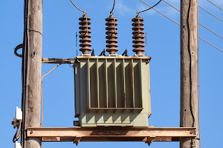
and delivering it at another voltage.
In this way they help achieve better transmission efficiency,
while transferring the power over longer distances
three-phase transformer,
by starting from its simplest form.
The basic working principle a transformer is simple,
Electromagnetic induction.
According to this principle
a varying magnetic flux associated with the loop
will induce an electromotive force across it.
Such a fluctuating magnetic field can easily be produced by a coil
and alternating EMF system.
A current-carrying conductor produces a magnetic field around it.
The magnetic field produced by a coil
will be as shown in the figure.
With the fluctuating nature of the alternating current,
the magnetic field associated with the coil will also fluctuate.
This magnetic flux can be effectively linked to a secondary winding,
with the help of a core
made up a ferromagnetic material.
This fluctuating magnetic field will induce an EMF in the secondary coils
due to electromagnetic induction.
Since the turns are arranged in a series,
the net EMF induced across the winding
will be the sum of the individual EMFs
induced in each turn.
Since the same magnetic flux is
passing through the primary and secondary coils,
the EMF per turn for both the primary and secondary coils will be the same.
The EMF per turn for the primary coil
is related to the applied input voltage as shown.
As a result the induced EMF at the secondary coil
is expressed as follows:
This simply means that with fewer turns in the secondary
than in primary one can lower the voltage.
For the reverse case one can increase the voltage.
But since energy is conserved,
the primary and secondary currents have to
obey the following relationship:
Three-phase transformers use three such
single-phase transformers,
but with a slightly different coil configuration.
Here the primary and secondary coils sit concentrically.
Two more such windings are employed in a three-phase transformer.
Transformers with high power ratings generally employ
a special kind of winding known as a Disc type winding,
Where separate disk windings are connected in series
through outer and inner crossovers.
The low voltage windings are connected
in a delta configuration.
And the high voltage linings are
connected in a star configuration.
Thus the line voltage further rises to
3^.5 times at high voltage side.
This also means that,
from a three-phase step up transformer
we can draw four output wires,
three-phase power wires and one neutral.
High-voltage insulated bushings are required
to bring out the electrical energy.
The core of the transformer is made of thin insulated steel laminations.
Such steel laminations are stacked together
as shown to form a three-phase limbs.
The purpose of thin laminations is to reduce
energy lost due to eddy current formation.
The low voltage winding usually sit near the core.
Various kinds of energy loss happens
while transferring power from the primary to secondary coil.
All these energy losses are dissipated as heat.
So usually the transformer is immersed in a cooling coil,
to dissipate the heat.
The oil dissipates the heat via natural convection.
Oil in the tank will expand
as it absorbs the heat.
A conservator tank helps to accommodate for this volume change.
To know more on
different types a transformer cores and windings.
Thank you !


0 Comments